2.1- Characteristics of the instruments
Analogue and digital sensors
The first aerial and satellite images of the Earth's surface were taken analoguely using cameras based on photographic film. Such films consisted of light-sensitive chemical emulsions and could thus capture visible light (and possibly near-infrared). For a long time, such aerial or satellite photographs were exclusively interpreted visually. Later, they were also scanned and digitally processed.
From the 1970s, digital, imaging sensors were placed aboard Earth observation satellites. These convert the intensity of the electromagnetic energy received in a given spectral band at a given part of the Earth's surface into an electrical signal that is then converted to a numerical value. Recordings in digital format made it possible to analyse parts of the electromagnetic spectrum other than just visible light and near-infrared. Moreover, the recordings made can be transmitted from the satellite to Earth via a radio link and in the form of a sequence of binary information. At the receiving station, the images are compiled so that they can be analysed using digital image processing techniques. These processing techniques became increasingly efficient over the years.
Imaging versus non-imaging sensors
We can also divide the sensors used in remote sensing into imaging and non-imaging types. A non-imaging sensor measures radiation coming from all points in the field of view and integrates them into a single value. Thus, the result consists of point measurements rather than an image since only a single value is generated per observed point.
Several instruments used in the field of remote sensing are non-imaging. For example, a radiometer, spectrometer and a spectroradiometer are devices often used for calibration. They are deployed in a lab or can be taken during field research to determine detailed spectral signatures of particular materials. For example, we can measure how much light it reflects in certain parts of the spectrum for each type of material found in our study area.
Another commonly used, non-imaging sensor is lidar, which allows laser altimetry and distance measurements. With lidar, one obtains a point cloud in space created by the reflection on the objects in this space.
|
A non-image-forming sensor measures the radiation coming from all points in the field of view and integrates them into a single value. Consequently, no image is formed. We can think of this as point data since only a single value is obtained from a given observation point. A mobile Doppler radar or speed-gun set up by the police to monitor speed is an example of an active, non-imaging sensor. The device emits pulses of radiation and the data generated is simply the speeds of vehicles passing by. No images are taken by this device; the speed camera may take care of that. Imaging sensors, on the other hand, measure radiation at different points of the target and that information can be processed into an image. There are two distinguished types of imaging sensors: the CCD (Charge Coupled Device) and the active pixel sensor or CMOS (Complementary Metal-Oxide Semiconductor). |
Imaging sensors form a digital image of their field of view reflecting spatial differences in the intensity of the radiation received. They essentially do this by converting electromagnetic radiation into an electrical charge using an integrated circuit consisting of a large number of capacitors.

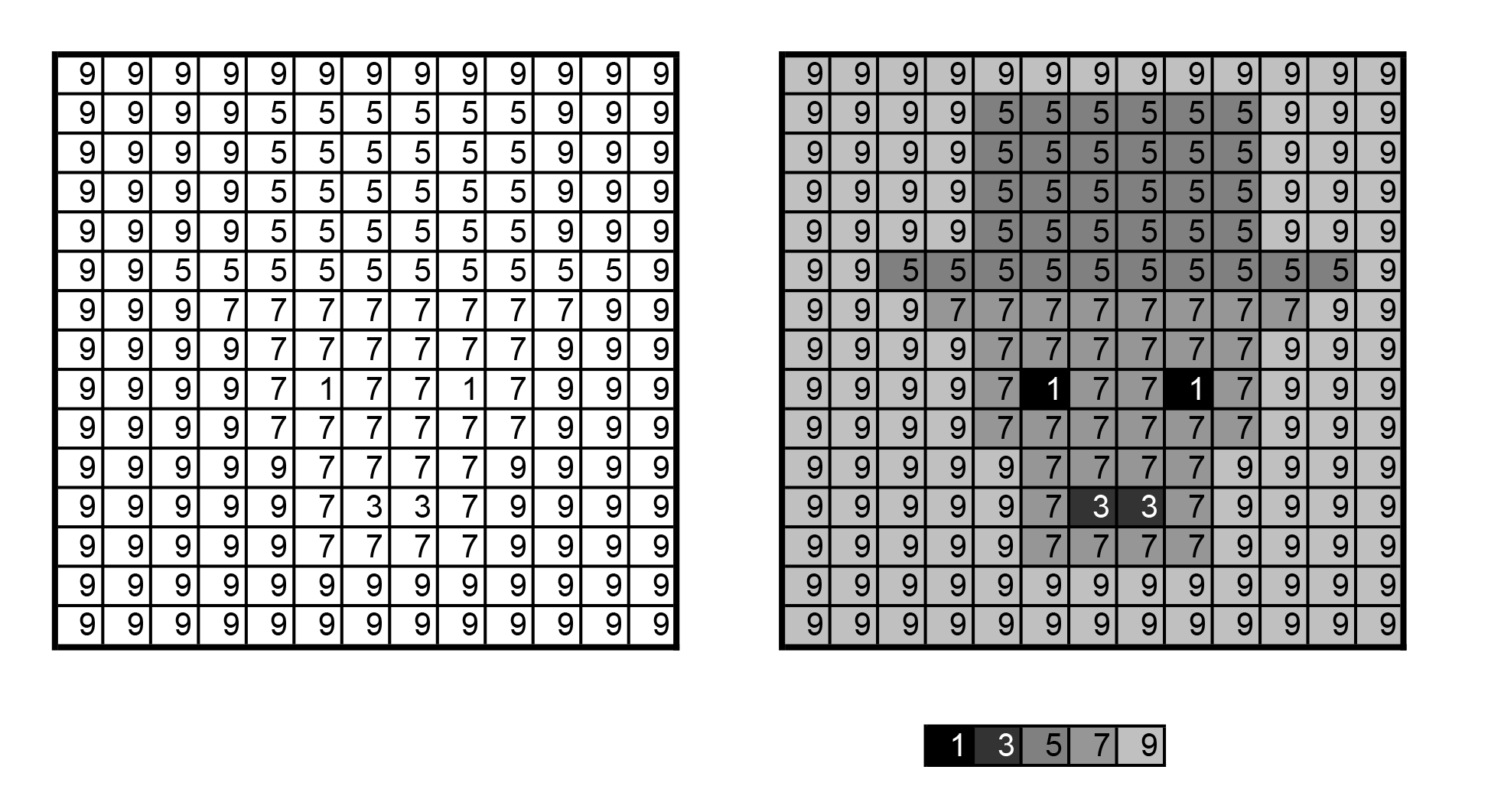
A digital image can be imagined as a matrix of numbers, where each number represents the intensity of the radiation perceived by the sensor at the location corresponding to a particular cell in the matrix. A cell in the matrix is called a pixel. The imaging sensors used for remote sensing usually produce images composed of several matrices.
In other words, there are multiple values for each pixel. This is because we measure the reflected (or emitted) energy in different parts of the spectrum. For example, an image from the Pléiades satellites will consist of four image matrices: one for the blue, green, red and infrared parts of the light. Imaging sensors can be divided into optical (including thermal-infrared) or radar sensors depending on the part of the spectrum in which they take measurements.
Passive and active sensors
Traditionally, remote sensing distinguishes between active and passive sensors. Passive sensors make use of naturally occurring light. In other words, they measure electromagnetic radiation that objects reflect or emit from the earth's surface. This can be, for example, near-infrared radiation emitted by the sun and reflected by a tree or thermal-infrared radiation emitted by poorly insulated roofs.
Active sensors, on the other hand, use their own energy to "illuminate" part of the Earth's surface. The emitted radiation that returns to the sensor after interacting with objects then serves as the basis for perception. Active sensors use certain microwaves (radar) or visible and near-infrared light (e.g. laser rangefinder, LiDAR). As sensor technology evolves, it is not inconceivable that the boundaries between active and passive sensors will blur through integration of both methods.
These two types of sensors are further explained in the section 'Main types of instruments'.
Angle and distance sensors
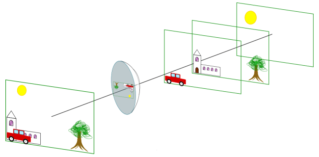
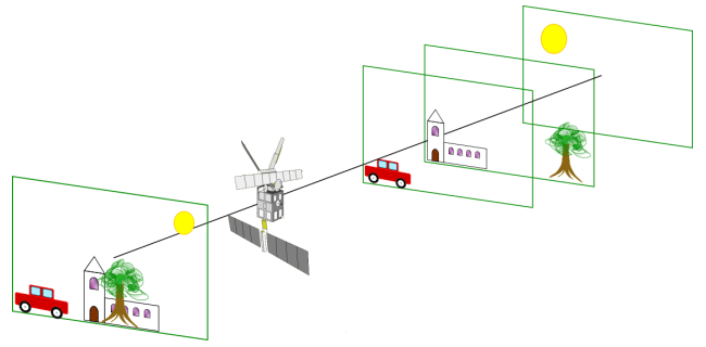
An optical instrument works like the human eye and has angular vision. This makes it possible to distinguish objects located at different angles, regardless of the distances at which they are located. In contrast, an active instrument, such as radar, measures distances and not angles. Therefore, two objects located at the same distance from the sensor are imaged in the same image pixel even if they are at different angles to the sensor.
Schematised angle view and distance view - © Dominique Derauw
This difference in image acquisition leads to different types of distortions for the two methods. Optical images appear more natural to us because they are acquired by systems similar to the human eye. On the other hand, RADAR images appear distorted to us. However, both recording methods must eventually be corrected to project the obtained images onto a common mapping system.
Across-track and Along-track sensors
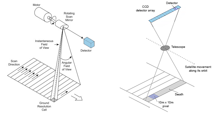
Unlike photographic (analogue) recordings, digital remote sensing systems use scanners. A scanner consists of imaging sensors with a narrow field of view (Instantaneous Field of View - IFOV) that systematically scans the terrain. Thus, the sensors compile a two-dimensional image of the Earth's surface for a given strip (swath) under the aircraft or satellite. Such scanning can be done in two ways: perpendicular to the flight path (whiskbroom) or along it (pushbroom).
Two scanning methods : over the flight path (left) and along the flight path (right).
Source: Grundlagen Fernerkundung - 7 -Earth Resource Satellites – part I
Scanners operating transverse to the direction of flight scan the Earth's surface in a series of lines perpendicular to the platform's direction of movement. A rotating mirror moves the field of view from one side to the other of the sensor while meanwhile the platform continues on its course. Successive scan lines thus form a two-dimensional image of the Earth. The sensors of previous Landsat satellites used this scanning technique. Although calibration was easier, the fragility of the fast-moving parts proved to be the major drawback of this design.
Following problems with a faulty scan line corrector aboard Landsat-7, successors 8 and 9 were fitted with a pushbroom system that scans along the flight path. Such systems also use the forward motion of the platform to scan successive lines perpendicular to the flight direction. Instead of a moving mirror that moves a few detectors across the terrain, there is a large number of aligned fixed detectors that can observe the whole strip at once. Such a system is lighter and the detectors continue to observe over a given area for longer, but it is more difficult to calibrate. Landsat's European colleagues, the Sentinel-2 satellites, also use such a system.


